BF++ Toys
- Details
- Written by Luigi Bianchi
- Hits: 5063
BF++ Toys [Quitadamo et al. 2007] is a collection of software tools and utilities developed to analyse, optimize and design Bio-Feedback and Brain-Computer Interfaces. They are a part of the BF++ framework (Bio-Feedback in C++ [Bianchi et al 2003]) which is itself a part of the NPXLab Suite. They can be obtained at www.brainterface.com. Once installed on your computer they are accessible from the Windows Start menu.
According to the Mason model [Mason, 2003] (Fig. 1), a Brain Computer Interface system (and more in general a Human Computer Interaction system) is formed by a Transducer (TR, which includes the acquisition stage and the Classifier) and a Control Interface (CI). A TR is responsible to acquire physiological data (e.g. by means of EEG, EMG, EOG, etc..) and convert them into logical symbols (LS) which in general have no semantic symbols but that represent the output of the classifiers. For example, if a subject is asked to perform some mental tasks such as a computation, or the imagery of a motor task, then to each of these mental tasks a logical symbol is usually associated. In general there is a 1 to 1 correspondence between a LS and a mental task that is detectable by a classifier. The set of LSs that can be outputted by the classifier represent the Logical Alphabet (LA) of the Transducer. Finally, a TR is characterized by an Extended Confusion Matrix (ECM) in which the results of the classifications performed by a TR are summarized.
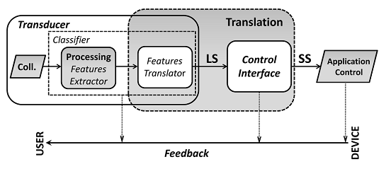
Fig. 1 - Logical scheme of a Human-Computer Interaction system.
The CI, instead, is responsible to convert LSs into Semantic Symbols (SS) which have a specific meaning and that can be used to perform a specific predefined action. It should be noted that a CI does not directly deals with brain or physiological signals, but just LSs and SSs. The complete set of SS that can be generated by a CI represents the Semantic Alphabet (SA). A CI is characterized by an encoding which is a map of SS into sequences of LS. Similarly to a LA, a SA is a collection of symbols, but in this case to each symbol (which is mapped to a real action such as switch on the light, write the ‘P’ letter, etc...) a probability of occurrence can be associated (see [Bianchi et al. 2007]).
As an example, in classical P300 spellers [Krusienski et al, 2008] characters are disposed on a 6 by 6 matrix (Fig. 2) and all of the characters of a row or a column flash in a pseudo-randomized order (the 4th row in the figure).
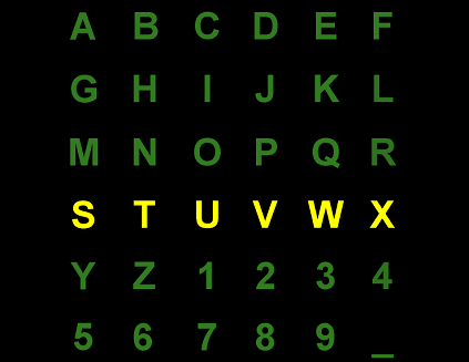
Fig. 2 – The typical virtual keyboard of a P300 Speller
The user is asked to fixate a characters and from the evoked responses to each of the flashes (12, 6 for the rows and 6 for the columns) it is possible to detect which characters he was attending. In this case the LA is formed by 12 symbols (the 6 rows plus the 6 columns) while the SA is formed by 36 characters (the symbols in the matrix). Two LSs (one row and one column) are necessary to select a SS. For example, the encoding of the P character is {3rd row, 4th column}.
The BF++ Toys are a set of tools and utilities aimed at analyzing, tuning, and designing BCI and HCI systems. The only entities that they handle are the two alphabets, the encodings and the ECMs. These four elements can completely (statically) characterize a BCI system. Each of the Toy reports a version number on the main form. Please, use this version number for every communication with the BRAINTERFACE developers team.
BF++ Toys include:
The Alphabet Builder Toy;
The Confusion Matrix Generator Toy;
The File Simulator Toy;
The Live Board Toy;
The Encoder Generator Toy;
The Simulator Board Toy;
The Optimizers Toys;
The Performance Metrics Toy.
- Details
- Written by Luigi Bianchi
- Hits: 4736
The Alphabet Builder BF++ Toy allows you to create logical and semantic alphabets for your Bio-Feedback and Brain Computer Interface applications. All of the other Toys will handle at least one alphabet so this is the first Toy that is executed, unless you find one among those provided with the BF++ Toys distribution.
From the Windows menu select and run the Alphabet Builder Toy. A form like the one illustrated in Fig. 1 will appear: it allows you to load or create logical or semantic alphabets of either characters or strings.
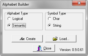
Fig. 1 – The main form of the Alphabet Builder Toy
A “Char” is a symbol as the one that you can type with your PC keyboard, whereas a “String” is a collection of chars. On some cases logical symbols are represented with chars (e.g. uppercase letters like “A”, “B”, “C” to represent three different mental states). On others they are strings (e.g. “MotorImagery”, “Computation”, “R1”, “R2”, etc..).
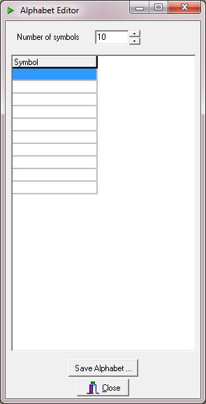
To create an alphabet, select either the desired type (Logical or Semantic) or the Symbols type (Char or String). Then press the Create button and a form like the ones illustrated in Fig. 2 (left: “Logical Alphabet”, right: “Semantic Alphabet”) will appear.
 |
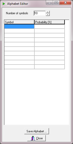 |
Fig. 2 – Logical (left) and Semantic (right) Alphabet Editor Forms.
The only difference among the LA and SA Editor Forms are the additional column (“Probability [%]”) in the case of the SA which can be optionally filled with the probabilities of occurrence of each SS. For example, if the SSs are the characters reported in fig. 3, then “Probability” means the probability of occurrence of a symbol in a specific language (e.g. the probability of occurrence for the ‘E’ letter in the English dictionary is 10.08%). There is no need to create an alphabet for the English and Italian languages as they are already provided in the distribution.
After selecting the number of desired symbols one can start to populate the grid. In Fig. 3 it is reported a logical alphabet formed by 12 symbols that can be used to represent the P300 Speller described earlier.
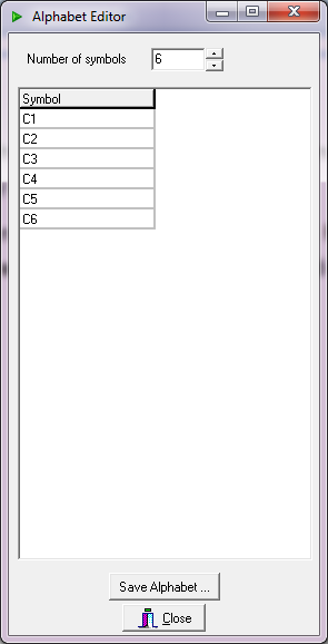
Fig. 3 – LA for the P300 Speller of Fig. 3
After done, one can (have to!) save the work done by pressing the “Save Alphabet” button. A standard save Dialog Box will appear allowing to select the proper name and path for the file. The file extension is “*.abl” for the logical alphabets and “*.abs” for the semantic ones. Data are stored using the XML technology.
This is all. All of the other Toys will use at least one alphabet (logical or semantic).
- Details
- Written by Luigi Bianchi
- Hits: 4434
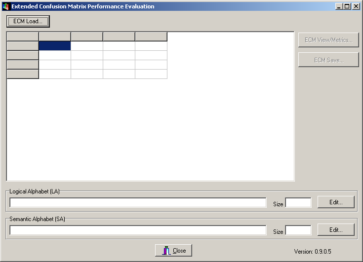
The Performance Metrics Toy is a simple tool which allows to compute several metrics from an Extended Confusion Matrix (ECM) which characterizes a Transducer. To use it it is sufficient to launch it from the BF++ Toys Windows Start menu (Start | NPXLab | BF++ Toys | Performance Metrics). The following form will be shown. The only thing you have to do is to load a file, by pressing the "ECM Load..." button.
There are two kind of files that can be loaded:
1) A ECM file, generated by other BF++ Toys, such as the Confusion Matrix Generator BF++ Toy.
2) A Classification Sequence ASCII file in which two columns of labels are reported, the first one that describe the desired classifier output, and the other one the corresponding actual output. An example of this kind of file is the following one (C1 to C6 represent classes, or the Logical Alphabet):
-----FILE BEGIN-----
C1 C1
C1 C5
C2 C2
C5 C5
C3 C3
C2 C2
C4 C3
C4 C4
C5 C5
C3 C3
C2 C2
C6 C6
C4 C4
C6 C6
C5 C5
C4 C4
C2 C2
C3 C2
C1 C1
C5 C5
C1 C1
C4 C4
C3 C3
C5 C5
C6 C4
C2 C2
C3 C3
C5 C5
C6 C6
C4 C4
C1 C1
C1 C4
C2 C2
C2 C2
-----FILE END-----
In the previous sample file the first desired output was C1 and actually it was correctly classified as C1, whereas the second one was misclassified as C5, instead of C1, and so on.
From this sequence file this Toys can deduce the ECM and also the Logical Alphabet, which is the set of classes (labels) included in the file (C1, C2,... C6 in the example).
Note that this version (0.9.0.5) does not allow to use the space character to define labels so that "C 1" is interpreted as "C" and "1" (two separate symbols). Future versions could overcome this limitation.
Once the file has been loaded, the form will appear as the following one:
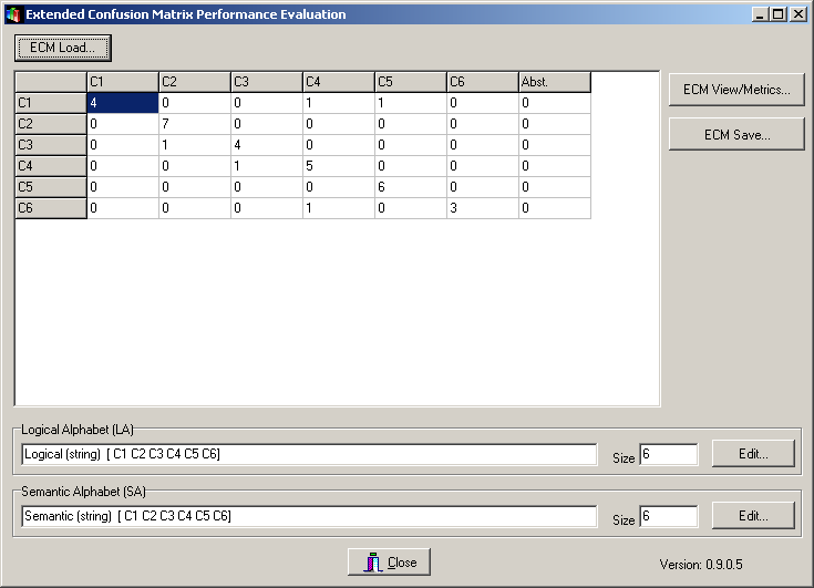
Note that regardless the file type loaded an ECM is represented (and can be edited by hand) and two alphabets (a Logical, LA, and a Semantic, SA, one) have been deduced. You can save these three entities (ECM, LA, SA) into files to be loaded from other BF++ Toys.
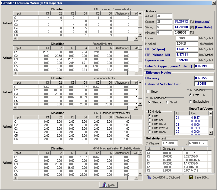
By pressing the "Metrics..." button you'll invoke the ECM Inspector, that will look like the following one:
- Details
- Written by Luigi Bianchi
- Hits: 6017
A control interface is characterized by an encoding, which is a mapping of a list of LSs into a SS. Different encodings can be used with the same transducer provided that they can handle the same logical alphabet. In fact, a logical alphabet represents the interface among transducers and control interfaces: the output of the former is the input of the latter. Furthermore, as described in [Bianchi et al., 2007] the performances of a complete system depend on the way a transducer and a control interface adapt themselves. Thus, it follows the need of having many encodings in order to choose the best one for each application and for each user.
The Encoder Generator toy is a tool that allows to build a virtually unlimited number of encodings according to many different strategies. After running it from the BF++ Toys menu the form illustrated in Fig. 1 will appear:
![]()
Fig. 1 – The Encoder Generator main form
The two entities that are necessary for building an encoding are the logical and semantic alphabets, which are the input and the output of a Control Interface. Then, according to them, many different rules can be applied to generate different encodings.
Once the two alphabets have been loaded (after pressing the corresponding “Load” buttons), the previous form will appear as the one illustrated in Fig. 2:
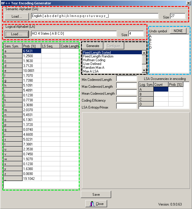
Fig. 2 – The Encoder Generator main form with the loaded alphabets
On the two top main rows (surrounded by a red rectangle) some description of the alphabets is provided, while in the large left grid (surrounded by a large green rectangle) the semantic alphabet is listed with also the probabilities of occurrence of each symbol. From the logical symbols it is possible to select one of them to be used as an UNDO key (blue rectangle). This character will be excluded from the encoding and will be used just for correcting errors. Finally, in the central part, it is possible to select which strategy should be used to generate an encoding (black rectangle). You can play with them. Once configured these options, after selecting the ‘D’ logical symbol as the UNDO key, and after pressing the “Generate” button, the same form will appear as the one of Fig. 3:
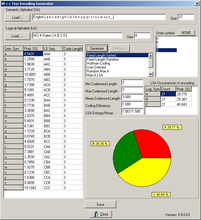
Fig. 3 – The Encoder Generator main form with a computed encoding
Some metrics is provided as well as the corresponding probability of occurrence of each logical symbol (see also the piechart), that is computed from the probability of occurrence of each semantic symbol. The occurrence on the UNDO symbol cannot be computed at this stage because the probability of making an error depends on the transducer (and then on the Extended Confusion Matrix). Other BF++ Toys, such as the Optimizers, will do it. Once generated, the encoding can be saved on a file by pressing the Save button and using the File Save Dialog Box. Again, the XML technology is used store the data.
- Details
- Written by Luigi Bianchi
- Hits: 4526
BF++ Simulators are a reliable way to identify the best combination of TRs (described by ECMs) and CIs (described by encoders) in a virtual keyboard application. However, in order to have consistent results, it is necessary to encode long semantic sequences. This could require several hours of processing time on a Desktop PC if the number of encoders or ECMs to be tested is huge. A better solution is to adopt the metric described in [Bianchi et al., 2007], which requires just few seconds to determine which TR and/or CI to choose to build the best system. In a typical situation one can choose which encoder should be assembled to a TR to build the best system. The Optimizer Toy is devoted to this: it computes the efficiency of a system built by combining a TR with a set of encoders and by performing all the possible permutations among the LSs of the LA. This produces the list that appears in the bottom part of the form of Fig. 1: the various combinations indicate that the best encoder to associate to the ECM selected in the top grid of the form is the Encoder 7, first permutation, with the δ symbol associated to the Undo key. This system will require on average the selection of 3.614 LSs to generate a correct SS. In an ideal system, that is a system that makes no errors, just 3 LSs are necessary so, on average, additional 0.614 selections are required to recover from mistakes.
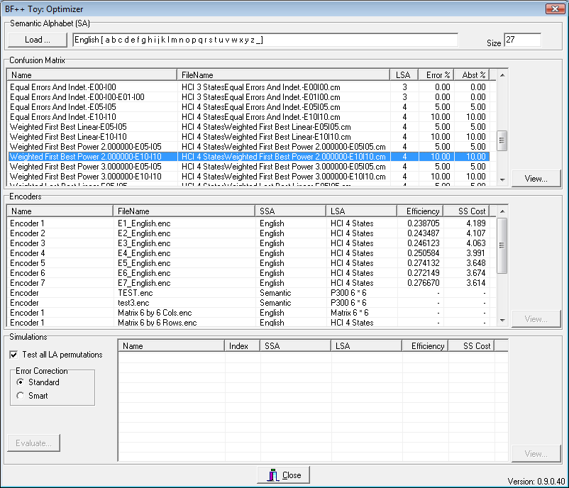
Fig. 1 – The main form of the HCI Optimizer #1
A more practical way to optimize a system is to start from the subject’ performances, that is a real ECM and to find which encoder should be bound to it in order to obtain the best system. For this reason another optimizer (see Fig. 2) was developed which works in this way: once one has identified the alphabets and provided the ECM, then a huge number of encodings are randomly generated and the overall system metric is computed. Less than 1 ms is necessary to generate an encoder and to evaluate the system which uses it (on a PC equipped with a 2.4 GHz Pentium 4), so that about a hundred of thousands of different encoders and systems can be evaluated in less than two minutes. For example, for the ECM described in Fig. 2 we started with an encoder which required 4.698 LS selections to generate a correct SS, but we were able to reduce it to 4.02 in less than two minutes after using this optimizer, thus boosting the performance of a whole system by more than 15%. It is important to underline, however, that the improvement depends on the error distribution over the ECM: the more uniform it will be, the lower the improvement will also be.
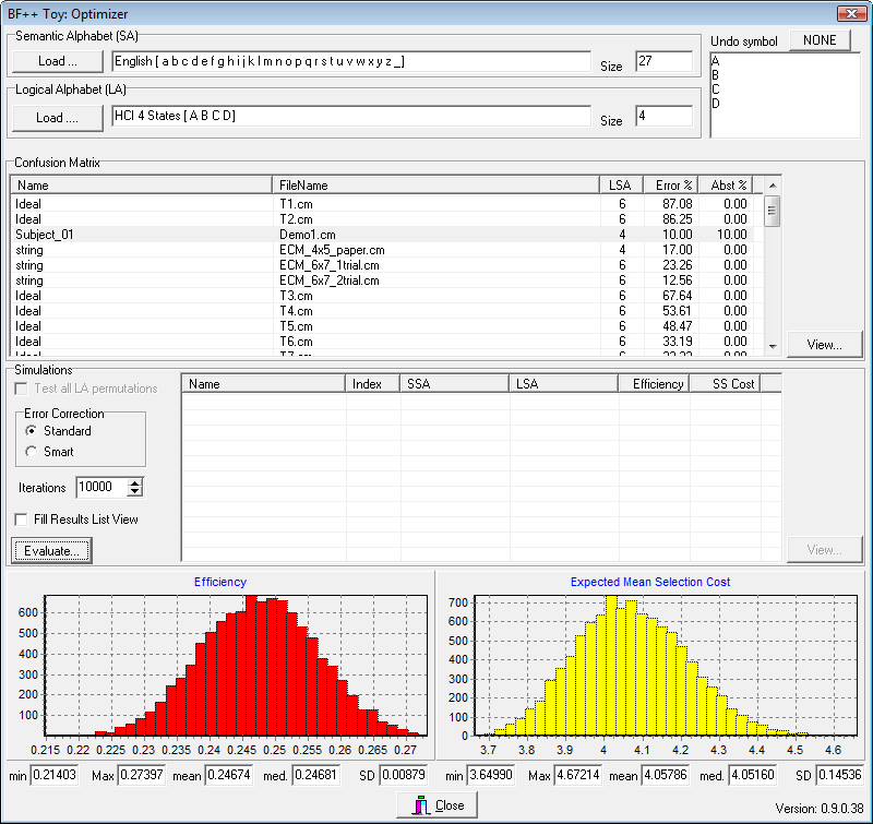
Fig. 2 – The main form of the HCI Optimizer #2